Design of Mobile Ad Hoc Network Terminal System Based on GPS15L
Abstract: The ultimate goal of wireless communication is 5W. The mobile ad hoc network (MANET) based on TD-SCDMA is a personalized communication method with great development potential, and the global positioning system provides extremely powerful assistance for communication and navigation. Combined with the national "863" research project, the TD-SCDMA mobile ad hoc network terminal system based on GRS15L is studied, the possible problems in the design are analyzed, the design ideas and methods are provided, and the future direction of the system design is indicated.
Mobile Ad Hoc Network (MANET) is a wireless communication network composed of mobile nodes that can directly communicate with each other without central control. MANET based on TD-SCDMA is a self-organizing network designed under the condition of fully utilizing the wireless resources of TD-SCDMA cellular network. The mobile terminal based on TD-SCDMA MANET can not only carry out internal information exchange, but also be able to access the TD-SCDMA cellular network and then connect to the Internet. This paper designs the TD-SCDMA ad hoc network mobile terminal based on GPS15L from the perspective of the underlying hardware, software and protocol.
1 MANET terminal system overall design
Unlike the German FleetNet mobile ad hoc network [1], MANET based on TD-SCDMA does not have a fixed gateway, independent frequency resources, and separate wireless transmission technology (RTT). Therefore, the mobile terminal (MT) software and hardware platform, communication protocol design and networking methods are quite different from FleetNet. At the same time, due to the lack of coordinated control on the network side (including Node B) of each mobile terminal of MANET based on TD-SCDMA, MT can act as a mobile terminal of pure MANET or an ordinary user equipment (UE) of TD-SCDMA cellular network Or a gateway (GW) integrating MT and UE. Therefore, the design of the MANET terminal system is more complicated and esoteric than the ordinary UE system. 
Making full use of existing research results is the primary principle of system design. On the hardware platform, the OMAP1510 development board (including handwriting display color screen, keyboard, mouse and other peripherals) and GPS module are added to the original field test mobile station (FTMS; equivalent to UE). In order to enable the added external devices to coordinate with the original FTMS, the corresponding hardware interface and driver software must be added. At the same time, the protocol software from the physical layer to the application layer needs to be modified or rewritten accordingly.
The design of the MANET mobile terminal system based on TD-SCDMA is carried out in accordance with the principles from overall to partial, first summary design to detailed design and concurrent design of software and hardware.
2 Hardware and interface design
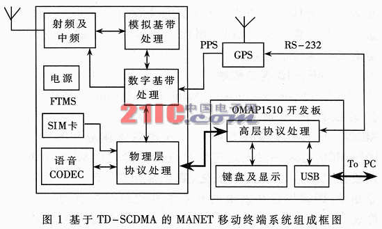
The MANET mobile terminal system based on TD-SCDMA consists of the following parts: radio frequency and intermediate frequency module, analog baseband processing module, digital baseband processing module, protocol processing module, voice codec module, SIM card and power management module, keyboard and display module , GPS module, PC interface module and power supply. Its composition and mutual relationship are shown in Figure 1.
2.1 GPS15L module
Why use Global Positioning System (GPS)? GPS is the most concise and efficient device that enables TD-SCDMA-based mobile ad hoc networks to communicate normally. The "S" in TD-SCDMA stands for uplink synchronization, that is, all user equipment (UE) signals sent to the Node B (base station) arrive at the Node B at the same time. Because the mobile ad hoc network is a network without central control, the communication between the nodes of the mobile ad hoc network based on TD-SCDMA needs a unified time mark, so that the signal reception and transmission between each terminal are at a certain beat Perform (frame synchronization). GPS15L of American GARMIN company provides pulse per second (PPS) with an accuracy of ± 100ns. Using this feature, when a second pulse arrives (rising edge), it is defined as the starting point of every 200 5ms wireless subframes. Here the role of PPS is equivalent to the DwPTS sent by Node B. 
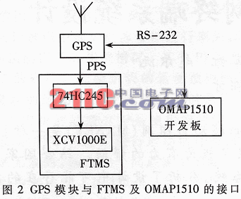
In addition to providing PPS, GPS15L also provides time information and geographic location information through the RS-232 interface, which is extremely beneficial to the design of power control algorithms and routing algorithms. With the relative position of the other party, the terminal is more accurate, reliable and reliable when calculating the transmit power, and routing addressing is more purposeful. The interface of GPS15L is shown as in Fig. 2.
After the GPS PPS is sent to the FPGA, it is compared with a 5 ms frame interrupt (frame synchronization) counter. If there are more than 200 frame interrupt signals between the two PPSs, the frame interrupt counter value is decreased, otherwise the count value is increased until there are exactly 200 frame interrupt signals.
GPS location information is sent directly to the OMAP1510 development board, which is processed by the high-level protocol running on the development board. In addition, the serial rate of GLS15L can be adjusted, and its optimal working rate can be adjusted by OMAP1510 with certain commands (the default value is 4800bps). Because the position information sent by GPS is not active, it is necessary to write appropriate instructions to read this information regularly.
2.2 OMAP1510 interface module
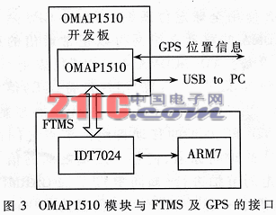
OMAP (Open MulTImedia ApplicaTIon Platform) is a high-performance open multimedia application platform with integrated TMS320C5510 digital signal processor and ARM9 RISC processor produced by TI. DSP + MUC is the inevitable trend of embedded applications in the future. OMAP1510 development board provides embedded operating system, color display, keyboard and mouse and other peripherals, so it will replace a protocol PC and an application PC currently configured in future development, making FTMS more mobile Sex and reliability. The interface is shown in Figure 3.
The interface between OMAP1510 and GPS is relatively simple. It obtains position information from GPS via RS-232 interface. The location information is processed by ARM9 in OMAP and sent to the routing layer running on it. OMAP1510 exchanges data with dual-port random access memory (DPRAM) and FTMS physical layer control chip ARM7. 
OMAP1510 also provides a USB interface, use it for pre-simulation debugging. The initial routing and application layer protocols will run on the PC. In order to enable high-speed data exchange between PC and OMAP1510 (at least 144kbps is required), USB bus is used. When these protocols are successfully run, they will be gradually ported to OMAP1510. Therefore, USB is only transitional in nature here.
2.3 USB interface module
The USB controller on OMAP1510 can work in master mode (Master) or slave mode (Slave). Here, it is only set to work in Slave mode, which allows external USB host devices to configure and read and write through the USB bus.
3 USB driver and application software design
In fact, the USB driver consists of two parts: the master USB driver working in the Sybian operating system (on the OMAP1510) and the slave USB driver working in Windows 2000 / XP (PC). Since the USB driver in the Sybian operating system is provided by the OMAP1510 development board supplier, you only need to design the USB driver and application in the Windows environment.
I designed these programs with WinDriver from Jungo [2]. First, use the KernelDriver 6.11 driver design wizard to complete the generation of driver source code (including installation information files). Then use VC ++ 6.0 and other C ++ language tools to edit, modify and compile these source programs to generate system files (.DLL or .sys). After the driver is generated, it also needs to be installed on the PC to test its reliability and stability. Finally, modify and compile with the application program generated by KernelDriver. Test the USB configuration of the compiled .exe file.
4 Design of MANET protocol software based on TD-SCDMA 
Similar to TD-SCDMA's MANET protocol stack, TD-SCDMA-based mobile ad hoc network protocol software consists of the physical layer (L1), physical layer control layer (L1C), radio link control (RLC) / media access control ( MAC) layer, logical link control (LLC), TCP / IP (including MANET routing) layer and application layer. Their mutual relationship and actual operation are shown in Figure 4.
L1 floor. The physical layer includes modules such as information coding, burst framing, user detection / joint detection, channel decoding, measurement and control. Because the mobile ad hoc network based on TD-SCDMA uses TD-SCDMA consistent wireless frame / slot structure and channel coding and decoding technology, their physical layers are basically the same.
L1C layer. The physical layer control layer includes public services, interface processing, and process control. It is mainly used to parse high-level commands and messages and convert them into commands (CMD) or requests (REQ) for L1. Receive data and signaling from L1, parse the data / signaling and forward the data or process it in this software.
RLC / MAC layer. This layer mainly does open-loop / closed-loop power control strategy, physical layer scheduling and automatic retransmission request (ARQ), etc. to ensure a certain link quality.
LLC layer. This layer is mainly used to control the logical link to make the link establish / maintain / remove the connection.
TCP / IP layer. This layer mainly implements MANET's IP allocation and binding, ad hoc network node routing / routing and transmission control. This layer and the application layer are currently on the PC, and the next step is to port them to the OMAP development board.
Application layer. This layer implements network applications such as HTTP and FTP.
The above briefly introduces the design of the mobile ad hoc network protocol stack based on TD-SCDMA. For more detailed information, please refer to the literature [3 ~ 4].
At present, the mobile terminal of TD-SCDMA ad hoc network based on GPS15L is under test, and there are many key technologies [5] that need to be tested and adjusted. Needless to say, future mobile terminals based on TD-SCDMA ad hoc networks will use long code (PN code) self-synchronization without GPS support. More and more in-depth research is needed on the terminal's power saving mechanism and wake-up mechanism.
Best Ethernet Cable for Gaming,Outdoor Ethernet Cable,Wireless Ethernet Cable,Best Lan Cable
Dong guan Sum Wai Electronic Co,. Ltd. , http://www.sw-cables.com