Wireless Transceiver Digital Transmission MODEM Module PTR2030 and Its Application
Pick   want:       This article describes the main features of the PTR2030 , pin functions, software design, hardware connections and specific application circuits. The PTR2030 is an ultra-small, ultra-low-power, high-speed wireless data transmission MODEM with excellent performance and is ideal for low-power wireless data transmission.
introduction
Since there are many types of wireless transceiver modules, how to select the required modules in the design is very important. The correct choice can reduce detours, reduce costs, and bring products to market faster. This paper introduces a new type of wireless transceiver. Module PTR2030 .
The PTR2030 is an ultra-small, ultra-low power, high-speed wireless data MODEM . It uses serial port transmission, application and programming is very simple, the transmission efficiency is very high; less peripheral components are required, the cost of product development is low; power consumption is small; the number of pins is small, the package is small, which is beneficial to reduce the PCB area and reduce the cost. .
PTR2030 is a combination of single ICs , receiving and transmitting one; using FSK modulation, strong anti-interference ability; standard DIP pin spacing, more suitable for embedded devices. In addition, because it uses a low transmit power and high sensitivity design, it can meet the requirements of wireless regulation and does not require a license. It is an ideal choice for low-power wireless data transmission.
Main features of the PTR2030
The pin diagram of the PTR2030 module is shown in Figure 1. The description of each pin is shown in Figure 1 .
PIN1 : VCC , positive power supply, connect 2.7~3.3V
PIN2 : CS , channel selection, must be set to high, ie CS=1 , that is, select the working channel as 315MHz
PIN3 : DO , data output
PIN4 : DI , data input
PIN5 : GND , power ground
PIN6: PWR, energy control terminal, when the PWR = 1, normal operation; if PWR = 0, the micro-power standby state
PIN7 : TXEN , transmit and receive control, when TXEN=1 , the module is in the transmitting state; when TXEN=0 , the module is in the receiving state
Software programming of PTR2030
In the software programming process, the selection of the working mode and working channel of the PTR2030 is particularly important. Table 1 shows the working mode control of the module and the selection of the working channel.
Sending part
PTR2030 communication rate of up to 20Kbit / s, also operate in other rates such as 4800bps, at 9600bps, no need to set the operating speed of PTR2030.
Before sending the data, the module should be placed in the transmit mode, ie TXEN=1 , and then the data of any length can be sent after waiting for at least 5ms (required for the conversion time of the transmission). After the transmission is finished, the module should be placed in the receiving state. , that is, TXEN=0 , the conversion time from transmission to reception is 5ms .
Receiving part
When receiving, the PTR2030 should be placed in the receiving state , that is, TXEN=0 . The received data can be sent directly to the serial port of the MCU or sent to the computer after level conversion.
Standby mode
When PWR = 0, PTR2030 enters the power saving standby mode, power consumption is about 8uA, but can not receive and transmit data in the standby mode.
Application of PTR2030 in temperature measurement and control system
The system consisting of PTR2030 can complete the point-to-point transmission of data acquisition, and can form a point-to-multipoint bidirectional data transmission channel. Figure 2 shows the circuit diagram of the PTR2030 used in the temperature measurement and control system.
In this system, the PTR2030 transmits the temperature data collected by the temperature sensor to the computer, and transmits the control signal sent by the computer to the single-chip microcomputer, thereby realizing the wireless data communication between the single-chip computer and the computer. PTR2030 can be directly connected to the serial port or I/O port of the MCU . When connected, the DI end of the PTR2030 wireless MODEM should be connected to the transmitting end of the MCU serial port , and the DO end should be connected to the receiving end of the MCU serial port. The I/O of the microcontroller can be used to control the module's transmit control, channel conversion and low power modes. When the PTR2030 is connected to a computer, it must be level-shifted to convert the TTL level to the RS232 level. Level conversion can be achieved with a single MAX232 .
Due to the characteristics of the wireless transceiver module , special attention should be paid to the formulation of the communication protocol and the handling of error correction when designing the software for the system. When there is no signal, the PTR2030 serial port outputs random data, so the first thing in the protocol is to be able to identify noise and valid data. Through testing and experimentation, 0xFF followed by 0x00 is not easy to occur in noise. Therefore, the start of data transmission by the MCU should be a byte of arbitrary content (this is because the first byte of data is easily lost when sent), then It is 0xFF followed by a 0x00 , and the receiving protocol stipulates that only packets starting with 0xFF followed by a 0x00 are received . Another problem to be aware of is the error correction of the data. In this system, the checksum method is used for error detection. Error correction uses a method of continuously transmitting three times. The same data is sent three times in succession. At the receiving end, each of the three data is compared. If at least two of the data are the same, the bit is correct. In summary, a complete wireless transmission protocol is: [ Start 1] [ Start 1] [ Start 2] [ Data 1] [ Data 2] [ Data 3] [ Checksum ] , Start 1 is 0xFF , Start 2 Is 0x00 , if the checksum is correct, it means the data transmission is complete, then compare data 1 , data 2 , data 3 , take the two identical, and give the response signal, if the data itself is incomplete transmission, no answer, the system The data will be resent.
Conclusion
The system consisting of PTR2030 can complete data acquisition of point-to-point transmission and point-to-multipoint bidirectional data transmission. Therefore, PTR2030 can be widely used in remote control, telemetry, wireless meter reading, access control system, cell paging, industrial data acquisition system, wireless tag, identity. Identification, non-contact RF smart card, small wireless data terminal, security fire protection system, wireless remote control system, biological signal acquisition, hydrometeorological monitoring, robot control, information appliances, wireless 232 , wireless 422/485 data communication and other systems. â–
references:
1. Â Â Â Â Â Â Â Yu Yongquan, ' ATMEL 89 Series Single Chip Microcomputer Application Technology', Beijing University of Aeronautics and Astronautics Press, 2002
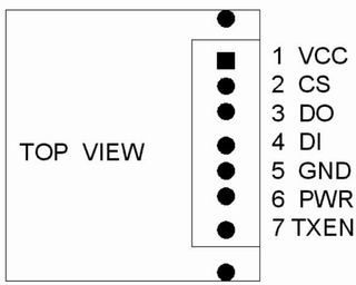
Figure 1 Â Â Pin Diagram of PTR2030 Module
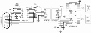
Figure 2 Â PTR2030 is used in the circuit diagram of the temperature measurement and control system
Permanent Magnets,Strong Magnets ,Powerful Magnets ,Industrial Magnets
Electromagnetic Equipment Co., Ltd. , http://www.nbmagnetools.com