Design of Automobile Steering Wheel Button Controller System Based on MCU
As cars become more popular in people's daily lives and the value of automotive electronics in automotive applications continues to expand, more and more comfort and "smart" applications are integrated into the field of body electronics. Freescale's latest automotive-grade 8-bit microcontroller, the MC9S08SC4, is the protagonist of this article. The microcontroller is the newest member of the industry's widely used Freescale HCS08 family of automotive-grade microcontrollers. Small package, but at the same time high performance and high reliability, suitable for many automotive electronics applications, such as: simple lighting control, button control, HVAC, LIN communication controller, interior rearview mirror dimming and simple Relay and motor control. If you are looking for a high-performance, low-cost automotive-grade microcontroller for your application, but are worried about the cost of electronic modules and PCB area limitations, I believe the MC9S08SC4 is exactly what you are looking for.
On-chip resources and performance of MC9S08SC4
The MC9S08SC4, a member of the Freescale HCS08 automotive-grade 8-bit microcontroller family, continues to have many of the advantages of the HCS08 microcontroller, such as the HCS08 core with a bus frequency of up to 20Mhz, and high-quality automotive-grade built-in flash memory for EEPROM emulation. The on-chip clock oscillator is calibrated to ±2% accuracy over temperature and voltage, and includes an internal enhanced serial controller that supports LIN communication. Figure 1 shows the internal block diagram and resource configuration of the MC9S08SC4 chip. 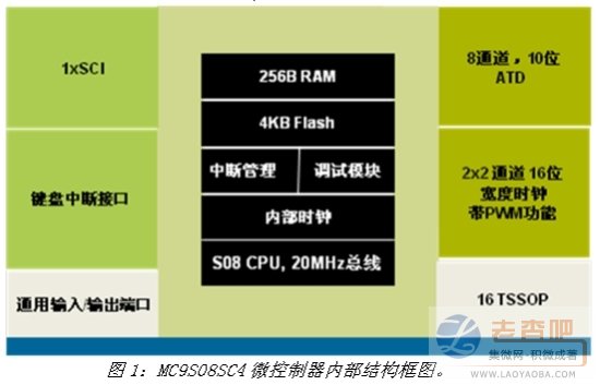
Typical application of MC9S08SC4
When people choose a family car, the requirements for comfort are constantly improved. Therefore, the comfort performance of the whole car is also paid more and more attention. The comfort performance has become an important indicator of the car purchase factor. So even in many low-end and mid-size cars, this demand can be seen everywhere. For example, the steering wheel of a car is now more than just a traditional control and speaker function. It is often integrated with buttons for controlling other functions. For example, control the radio's operation buttons, control buttons for controlling DVD or CD playback, mobile phone Bluetooth hands-free, auto-cruise control buttons, and even buttons that have user-configurable features. The different styles of the steering wheel buttons reflect the different personality of each model, so the button design is receiving more and more attention from the car manufacturers.
The MC9S08SC4 microcontroller introduced in this article is ideal for applications like steering wheel buttons, which can help automakers gain greater differentiation advantages than competitors without increasing the cost. The MC9S08SC4 can be used as a Slave node for LIN communication in keyboard applications. It is responsible for collecting various control signals from the steering wheel buttons and then transmitting these signals to other controller units in the car via the LIN bus. These controls include the body electronic controller. , CD or DVD controller, Bluetooth communication controller and dashboard controller.
Figure 2 shows the system block diagram using the MC9S08SC4 as the steering wheel button controller. It simply shows the complete control flow of the entire control system from the keyboard signal input through the logic control of the final output drive signal. The car steering wheel button controller unit consists of a blue frame interior. Although the structure of the entire control system is relatively simple, there are some design challenges in this application. 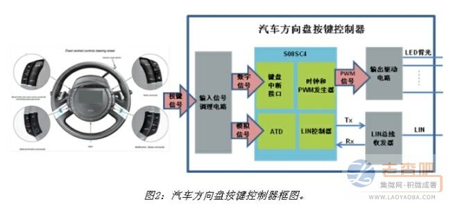
Automotive steering wheel button controller system design challenge
The main challenges in the design of the car steering wheel button controller are:
The steering wheel button controller is limited in the space of installation. Since the controller will be installed near the steering wheel panel, it is necessary to reduce the PCB area as much as possible in order to easily fit into a small space under the steering wheel, and Avoid conflicts with other modules such as the location where the ABS is installed.
The steering wheel button controller provides the driver with control comfort and driving pleasure, and needs to take multiple control commands from the button and send these commands to the corresponding control module, such as various CD/DVD related entertainment. Function, cruise control and hands-free function of mobile phone or telephone. If wire harness is used to connect these functions to the control object separately, it will increase the cost of a large number of wire harnesses and the weight of the whole vehicle, and a large number of wire harnesses will also increase the complexity of the wiring. To the extent that communication between modules is achieved by means of a car bus is a cost-effective option.
For cost-sensitive applications, how to minimize the number of external components and use the on-chip resources provided by the microcontroller to implement system functions is the key to design. But this poses a serious challenge to the performance of the microcontroller itself, especially for a car entry-level microcontroller.
How MC9S08SC4 responds to system design challenges
The MC9S08SC4 family of microcontrollers foresees the challenges of system design locks in similar applications at the beginning of the chip design. The following describes how the MC9S08SC4 overcomes these challenges one by one.
The MC9S08SC4 family of microcontrollers is available in a 16-TSSOP package that includes a pin size of only 6.40 x 5.00 mm2. The steering wheel keypad controller design will significantly reduce PCB area. On the other hand, since the MC9S08SC4 microcontroller has its own clock generator and is calibrated to achieve a maximum error of ±2% accuracy, even for this system. It is also capable of applications that require the highest clock accuracy (LIN communication). Based on the above analysis, the user can directly use the internal digital clock to provide the LIN communication and the clock signal required by the entire system, thereby eliminating the need to connect a crystal oscillator or a clock oscillator to the outside of the chip, thereby saving PCB area and system cost.
For the various control functions that the car steering wheel keyboard is responsible for, the LIN bus can also save the wire harness cost, reduce the weight and facilitate the function upgrade and cutting effect. As a low-cost, high-reliability automotive bus system, LIN is widely used in body electronics systems. Although the LIN controller can be implemented using a common serial port controller UART, the serial port controller on the MC9S08SC4. The SCI module not only implements the functions of the UART, but also integrates certain hardware features related to LIN communication, such as the generation and detection process of the very special Break domain in LIN communication. The function of this hardware integrated LIN communication is Compared with the use of ordinary UART controllers, users can reduce the complexity of LIN communication software design, speed up product development cycle and time to market.
Figure 3 shows the structure of the LIN communication data frame. The leftmost Break field is sent by the Master node in the LIN bus system to indicate the start of a frame of data. The corresponding Slave task of the LIN bus system needs to be correct. After the Break field is identified, the corresponding LIN communication process can be completed. At the beginning of each LIN bus communication, the Master node must generate a Break field to initiate a LIN communication. If this process can be done by hardware, the CPU workload will be greatly reduced. Otherwise, the Slave task will This difference also exists in the Break domain discrimination process. 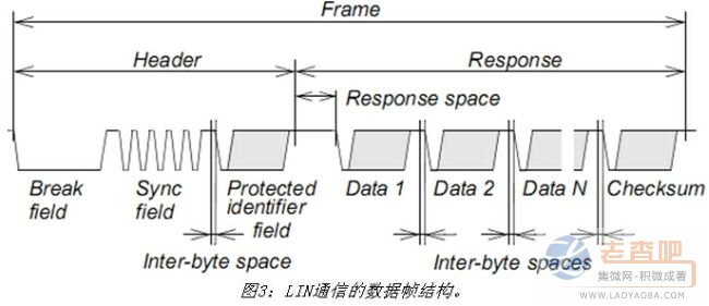
According to the LIN communication protocol, the Break field consists of at least 13 consecutive dominant level signals, which is also the only domain in the entire LIN data frame structure that does not follow the byte structure shown in FIG. Therefore, the generation and identification of the Break domain for the standard serial communication controller UART must be completed by means of software and other hardware means, which is a major challenge in software design. For example, when the Master generates the Break signal, the UART needs to generate a period of at least 13 bits by means of a timer channel, and then software controls the corresponding Tx port to output a dominant level during the timing period to complete a The generation of the Break field. Correspondingly, if the normal serial communication controller UART is used as a slave node, when it needs to detect the Break domain, the completion of this process also requires additional hardware and software means. 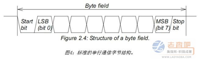
However, for the serial port controller SCI on the MC9S08SC4 microcontroller, if the MC9S08SC4 acts as the master node to generate the Break field, it only needs to operate by operating the SBK bit in the corresponding control register in the SCI; otherwise, when it acts as When the Slave node is used, it is possible to automatically identify whether there is a Break field on the LIN bus by querying the LBKDIF flag in the status register or by interrupt. In the MC9S08SC4, the generation and identification of the Break field of LIN communication is only realized by the user by operating the relevant registers, and then the actual operation process is completed in the background through the hardware of the SCI controller, as opposed to not having these hardware characteristics. The ordinary serial communication controller, MC9S08SC4 brings many advantages to users in software and hardware for implementing LIN communication.
In the car steering wheel button control system, some data, such as the last volume information before the system is powered down or the speed information of the cruise control, need to be restored after the next power-on. A common solution to this problem is to add a slice to the control system. EEPROM to save the corresponding data, but this solution brings the dual pressure of increasing PCB area and cost. Therefore, in the embedded system, the power-down data storage in the range of several tens of bytes is saved. The on-chip Flash emulation EEPROM is implemented in the microcontroller system.
However, not all Flash in the microcontroller can be used to simulate the operation of the EEPROM, because the operation of the Flash analog EEPROM is closely related to the internal structure and parameter characteristics of the Flash memory. The use of Flash memory to simulate EEPROM operation requires that Flash memory must have the following features: no external high voltage support is required for programming and erasing of Flash memory, that is, the microcontroller can directly generate high voltage to support programming and erasing. The course of operation. Flash memory needs to support higher repetitive programming and erase operation cycles. Of course, this parameter is closely related to the requirements of the entire system, that is, the number of parameters to be saved and the number of times of storage in the life cycle of the steering wheel button controller are closely related. Dynamically saving parameters to Flash during system operation requires the Flash controller itself to provide a corresponding register interface so that the user can program and erase through software.
For the above three requirements, the MC9S08SC4's Flash memory can be satisfied. The MC9S08SC4's Flash controller has its own high-voltage pump to support the voltage required for programming and erasing operations. For the Flash programming and erasing cycle problems, for example, In the steering wheel button controller system, 32 bytes of data need to be saved after power-down. If 1k of 4k byte flash is used for EEPROM simulation, then 320,000 power-down saves can be supported in the worst case. It can support up to 3,200,000 power-down saves. Of course, depending on the results of different application estimates, this requires the customer to choose a storage strategy based on the specific application to achieve as many times as possible. Table 1 shows the main performance parameters of the Flash memory in the MC9S08SC4 microcontroller. 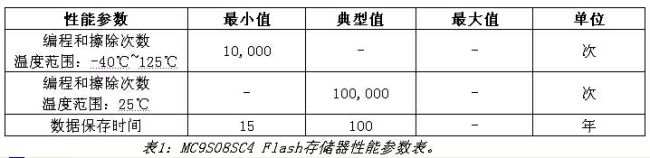
Summary of this article
This paper introduces the application of the car steering wheel button controller, reveals the main challenges that may be faced in the system design, and explains how the MC9S08SC4 as the main controller can overcome the design challenges by exploiting the advantages of the chip itself. Therefore, in automotive electronic systems, applications like the steering wheel button controller do not require the microcontroller to have very complex data computing capabilities and high real-time processing capabilities, but have limitations on the PCB area and mounting position. Sensitive to the cost of the control system, the system requires extended performance through the LIN bus and applications requiring automotive-grade product reliability. The 8-bit automotive-grade microcontroller MC9S08SC4 from Freescale Semiconductor is ideal.
This article refers to the address: http://
Function: The Led Head Lamp has 1-5 modes;
Feature: The LED Head Lamp usually high power and super bright;
Trait: The products are waterproof, shockproof and tactical;
Method of application: Simple on/off push button operation, or motion sensor;
Range of application: The LED Head Lamp for emergency events, camping, outdoor activities;
Adervantages: Our products are saled with factory price, and the quality can guarantee, lastly we provide warranty for 1 year.
LED Head Lamp
Led Head Lamp,Headlamp Torch,Led Headlamp,Led Head Torch
Ningbo Henglang Import & Export Co.,Ltd , http://www.odistarflashlight.com